VIO4+ Setup Guide
This Article Applies To
VIO4+ Series Servers
Configurations
VIO4+ = 4 in / 4 out (SDI) — locked configuration, no other I/O combinations available
What's in the Box?
Cablecast VIO4+ Video Playback Server
AC power cables
Micro-BNC to Standard BNC adapter cables
Out of Box & Setup
You will need an ethernet cable for internet access. This will also allow for a Cablecast Customer Success Manager (CSM) to remote in to your server and help with configuration.
Getting Started
Connect the server to power, ethernet, and a VGA monitor. Connect a keyboard and mouse via the USB ports.
Turn the server on.
The server will boot and go through the Windows 11 Out of Box Setup. You will need to create a Windows username and password during this process.
Be sure to note your Windows username and password. Cablecast support does not have a way to recover credentials other than to reimage the system.
Once into Windows, be ready for IO configuration (if needed) and Cablecast software setup.
AV Connections
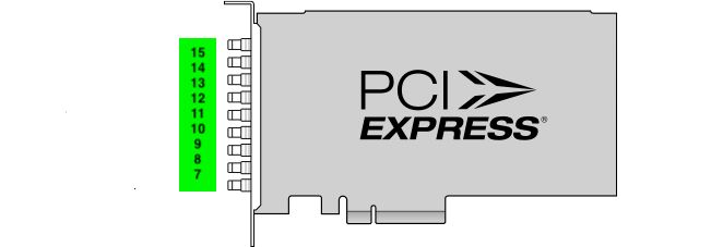
The VIO4+ ships in a locked 4x4 configuration (four inputs and four outputs). The connectors on the VIO4+ are Micro-BNC. Adapter cables included in the box allow you to go from Micro-BNC to Standard BNC. The ports on the I/O card are numbered from the bottom up (see Figure 2 below).
Connect a cable from Port 1 to an input on your SD/HD-SDI routing switcher.
Connect a cable from Port 2 to an input on your SD/HD-SDI routing switcher.
Connect a cable from Port 3 to an input on your SD/HD-SDI routing switcher.
Connect a cable from Port 4 to an input on your SD/HD-SDI routing switcher.
Connect a cable from Port 5 to an output on your SD/HD-SDI routing switcher.
Connect a cable from Port 6 to an output on your SD/HD-SDI routing switcher.
Connect a cable from Port 7 to an output on your SD/HD-SDI routing switcher.
Connect a cable from Port 8 to an output on your SD/HD-SDI routing switcher.
Connect house tri-level or analog blackburst to REF Port (bottom port — see Figure 2 below).
VIO4+ System Specs
FIGURE 1: The Cablecast VIO4+
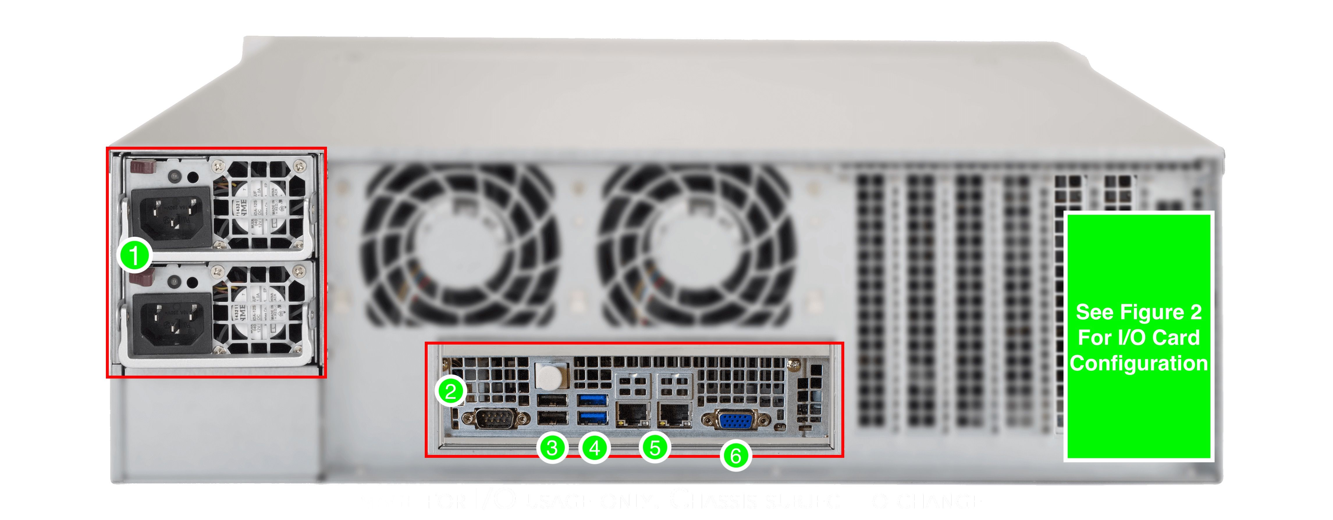
FIGURE 2: I/O Card
AC Power
RS232 COM port (male)
USB 2.0
USB 3.0
Ethernet
VGA
Reference In
Output 1
Output 2
Output 3
Output 4
Input 1
Input 2
Input 3
Input 4
Setting Up Audio Normalization
For device resolution and audio configuration, follow the Audio Normalization and Processing in Cablecast guide.
Cablecast CG Background Audio
Cablecast CG supports two background audio options. See the relevant article for your setup:
Setting Up USB Background Audio — for audio sources connected directly to the server via USB
Setting Up Network Stream Background Audio — for internet radio (Icecast) streams, with no additional hardware required
