VIO 2 Setup Guide
This Article Applies To
VIO 2 Servers
Configurations
VIO 2 = 1 in / 1 out OR 2 out (SDI)
What's in the Box?
Cablecast VIO 2 video server
AC power cables
Prerequisites
Before beginning setup, make sure you have the following available:
An ethernet network connection
A keyboard, mouse, and a VGA monitor
Your existing A/V infrastructure (at least one video monitor, if you're just testing)
Setup Overview
There are three parts to setting up your Cablecast server: Physical Setup, Software Setup, and Testing.
Physical Setup: You'll learn about the physical connections on the Cablecast server and how to tie it into your existing infrastructure.
Software Setup: You will be taken through the steps necessary to configure the input and output configuration of your VIO 2 server.
Testing: Finally, you'll run some simple tests to make sure the Cablecast server is correctly configured and ready to use.
Part I: Physical Setup
Physical Connections
On the back of your Cablecast server, you'll see several ports. Please refer to the diagram below for connections on your VIO 2 server.
System Connections
All Cablecast servers share some basic system connections:
Connect a keyboard and mouse via the USB ports.
Connect a monitor. The monitor is required for server setup, and we recommend that it remain connected. All Cablecast servers have at least a VGA port, and this is what we recommend connecting to the KVM in your rack.
Connect the Cablecast server to the network via one of the ethernet network jacks.
Connect the Cablecast server's power supply to an AC power source using the provided AC power cables.
AV Connections
Next, you will connect the Cablecast VIO 2 server to your video infrastructure.
The VIO 2 ships in a 1x1 configuration (one input and one output) from the factory. It can be reconfigured between 1x1 and 0x2 (zero inputs, two outputs) using the VIO IO Configuration Utility, which is covered later in this article.
Connect a cable from BNC 1 to an input on your SD/HD-SDI routing switcher.
Connect a cable from BNC 2 to an input or output on your SD/HD-SDI routing switcher, based on your needs. In 1x1 mode, BNC 2 would be your encoder and fed from an output on your routing switcher.
Connect house tri-level or analog blackburst to the REF BNC (far left in the diagram).
FIGURE 1: The Cablecast VIO 2
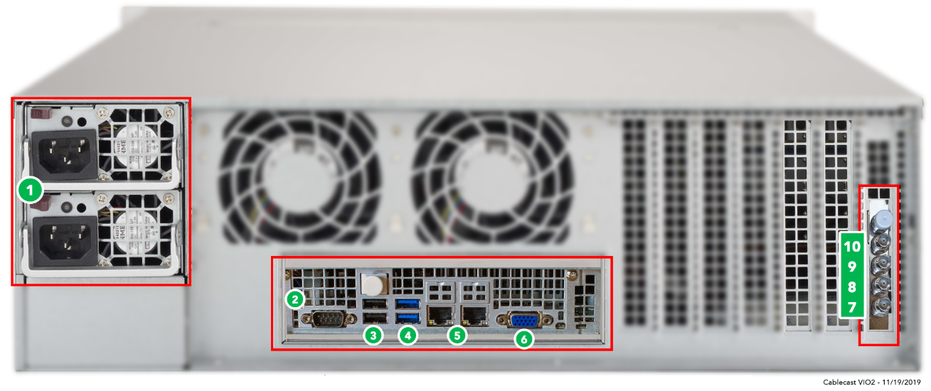
1. AC Power
2. RS232 COM port (male)
3. USB 2.0
4. USB 3.0
5. Ethernet
6. VGA
7. Ref In
8. Out 1
9. In 1 (or Out 2 when configured as 0x2)
Powering On
Once your Cablecast server is connected, power on the server by pressing the power button on the front of the unit. The unit will boot and go through the Windows System Preparation process, during which you will be prompted to create a Windows username and password. Once you are in Windows, you will be ready for IO configuration (if needed) and Cablecast software setup.
Note
Be sure to note your username and password. Cablecast support cannot recover Windows credentials — the only option is to reimage the system.
Also note that if you plan to do network playback across servers, or configure a NAS to work with video servers/VOD, the Windows credentials across all servers must match.
Setting Up Audio Normalization
For device resolution and audio configuration, follow the Audio Normalization and Processing in Cablecast guide.
Cablecast CG Background Audio
Cablecast CG supports two background audio options. See the relevant article for your setup:
Setting Up USB Background Audio — for audio sources connected directly to the server via USB
Setting Up Network Stream Background Audio — for internet radio (Icecast) streams, with no additional hardware required
