VIOLite 600/700 Setup Guide
This Article Applies To
VIOLite Servers
Configurations
VIOLite = 1 in / 1 out OR 2 out (SDI)
What's in the Box?
Cablecast VIOLite video server
AC power cables
Prerequisites
Before beginning setup, make sure you have the following available:
An ethernet network connection
A keyboard, mouse, and VGA monitor
Your existing A/V infrastructure (at minimum, one video monitor for testing)
Setup Overview
Setting up your VIOLite server involves three phases:
Physical Setup — Connect the server to your existing infrastructure.
Software Setup — Configure the input and output settings for your VIOLite.
Testing — Verify that everything is working as expected.
Part I: Physical Setup
System Connections
Connect a keyboard and mouse to the USB ports.
Connect a VGA monitor. The monitor is required during setup, and we recommend keeping it connected. All Cablecast servers include at least one VGA port — this is also what you'll want to connect to a KVM switch in your rack.
Connect the server to your network via one of the ethernet ports.
Connect the server's power supply to an AC power source using the included AC power cables.
AV Connections
The VIOLite ships in a 1x1 configuration (one input, one output) from the factory. It can be reconfigured to 0x2 (zero inputs, two outputs) using the VIO IO Configuration Utility, covered later in this article.
Connect a cable from BNC 1 to an input on your SD/HD-SDI routing switcher.
Connect a cable from BNC 2 to an input or output on your SD/HD-SDI routing switcher, depending on your needs. In 1x1 mode, BNC 2 is your encoder input, fed from an output on your routing switcher.
Connect house tri-level or analog blackburst to the REF BNC (far left on the back panel).
FIGURE 1: The Cablecast VIO Lite
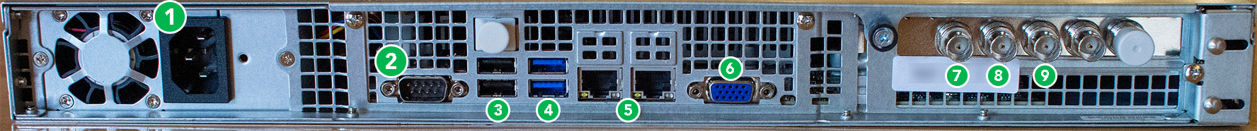
1. AC Power
2. RS232 COM port (male)
3. USB 2.0
4. USB 3.0
5. Ethernet
6. VGA
7. Ref In
8. Out 1
9. In 1 (or Out 2 when configured as 0x2)
Part II: Powering On
Once all connections are made, press the power button on the front of the unit. The server will boot and go through Windows System Preparation steps.
During this process, you will need to create a Windows username and password.
Important
Make sure to note your Windows username and password someplace secure. Cablecast Support cannot recover lost credentials — the only option is to reimage the server.
Part III: Software Setup
Server Configuration
Once your server is powered on and connected to the network, you'll configure it in Cablecast. This includes setting the input/output mode (1x1 or 0x2), creating or linking channel outputs, and configuring encode devices.
Configuring New Cablecast Servers
Audio Normalization
Follow this guide to configure device resolution and audio settings:
Audio Normalization and Processing in Cablecast
Cablecast CG Background Audio
Cablecast CG supports two background audio options. See the relevant article for your setup:
Setting Up USB Background Audio — for audio sources connected directly to the server via USB
Setting Up Network Stream Background Audio — for internet radio (Icecast) streams, with no additional hardware required
What's Next?
Once your server is configured, review these articles to continue your setup:
